A graph consists of nodes (a.k.a. vertices), and links between the nodes (a.k.a. edges) . A link connects two nodes. Sometimes one wants to draw more than one link between two given nodes. This might present, as it turns out, a programming problem e.g.when using the d3js force layout. In this post I present the problem, and two mathematical solutions. One solution uses trigonometry and is exact. The other solution uses only arithmetical operations but is an approximation (we shall see how approximate it is). I include an implementation of the two solutions in Javascript, inside a small example application using the d3.js visualization library.
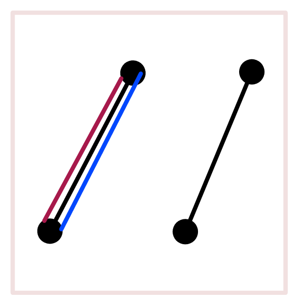 Figure 1
The d3.js force-layout makes the needed calculations for the target graph. The actual drawing (i.e. setting the DOM) is up to the force-layout user. The force-layout is given data in the following format:
{
nodes:
[
{…},
{…},
…
],links:
[
{ source: 1, target: 3},
{ source: 4, target: 5},
{ source: 4, target: 5},
{ source: 4, target: 5},
…
]
}
Each link has a source and a target properties, references to the two nodes at the two ends of the link. There can be multiple links with the same source and target properties, as in the example. If we display these multiple links as straight line segments between the end points, all the line segments will coalesce into one (figure 1, right side). This is because the mechanism provides us only with coordinates for the end points. The wanted outcome for us is to draw multiple lines between the two nodes (figure 1, left side).
We want to draw n parallel links between two nodes. While we don’t limit the number of such links, there will of course be a practical limit, according to the size of the drawing of the nodes. Each new link would be added to the sides of the first link alternately as shown in figure 2. Note the numbering that emphasizes the order of placement.
 Figure 2
Programmatically, this could be handled by preprocessing the links array, to assign to each link in a multiple-links-set a target-distance from the first link between the relevant two nodes (see method prepareLinks in the implementation). We could then use this target-distance in order to translate the link’s position.
As mentioned, I will present two methods to use this target-distance in order to calculate the placements of the multiple links.
The Exact Calculation
Given a line segment AB, we want to draw multiple links between points A and B. In order to draw a parallel line segment, we can simply add some translation to the coordinates of A and B. What we need to determine is how much to translate the segment AB, along the x and y axes.
We want the distance between the line segments to be some number s. s can be different values. Here I will make the plausible choice to have s equal the thickness of a line segment (it is exaggerated in figure 3).
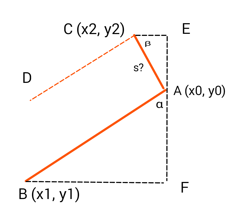 Figure 3
Our goal is to find the point C, so that the line segment CD, would be parallel to AB, and will have a distance s from AB.
It is not difficult to see that the two triangles AFB and AEC are similar. In particular the two angles α and β are equal. This fact could be used to compute the point C with trigonometry.
tan α = (x1-x0) / (y1-y0)
therefore
β = α = arctan [(x1-x0) / (y1-y0)]
and therefore
x2-x0 = -s cos β = -s cos (arctan [(x1-x0) / (y1-y0)])
y2-y0 = s sin β = s sin (arctan [(x1-x0) / (y1-y0)])
and we know x0, y0, x1, y1 and s, so that x2 and y2 can be computed.
Note: if y0=y1, we cannot divide by (y1-y0). But this is really a simpler case. Just setting x2=x0, y2=y0+s will give us the desired distance s.
In the programming example, the calculation is implemented as follows: It computes the required translation, in terms of x offset and y offset, such that the translated line segment will have the required distance to the given line segment.
function calcTranslationExact(targetDistance, point0, point1) {
    var x1_x0 = point1.x - point0.x,
        y1_y0 = point1.y - point0.y,
        x2_x0, y2_y0;
    if (y1_y0 === 0) {
        x2_x0 = 0;
        y2_y0 = targetDistance;
    } else {
        let angle = Math.atan((x1_x0) / (y1_y0));
        x2_x0 = -targetDistance * Math.cos(angle);
        y2_y0 = targetDistance * Math.sin(angle);
    }
    return {
        dx: x2_x0,
        dy: y2_y0
    };
}
The Approximate Calculation
Let’s return to the last figure.
Figure 3
Consider first the case when
|BF| > |FA|
(as happens to be in the figure) i.e.
|x1-x0| > |y1-y0|
Because triangles ABF, ACE are similar, it follows that
|AE| > |CE|, i.e.
|y2-y0| > |x2-x0|
Now, let’s set y2 to y0 + s, so that
|y2-y0| = s = |AE|
Setting y2 will also determine x2, because again, due to the similarity of the triangles
|y2-y0| / |x2-x0| = |x1-x0| / |y1-y0|
But what about the length of AC? Originally we wanted it to be equal to s. Now that we set the length of AE to s, the length of AC will be bigger than s, since AC is the hypotenuse of the right triangle ACE. Yet, how bigger than s will AC be? Remember that we are considering the case where
|AE| > |CE|
According to Pythagoras’ Theorem, we have
|AC|^2 = |AE|^2 + |CE|^2
< |AE|^2 + |AE|^2
= 2 s^2
Therefore
|AC| < √2 s
And therefore, although |AC| would miss the target s, it would not miss it by much. More precisely, we have
s < |AC| < √2 s < 1.42 s
So, in the case where we know that |AE| > |CE|, if we then set |AE| = s, it will turn out that
s < |AC| < 1.42 s
Now in the other case, where |AE| < |CE| we can get the same result by setting |CE| = s, instead of |AE| = s.
With the two cases put together, we have a conclusive and simple arithmetic method, given a line segment AB, to determine a point C, such that AC, the distance from C to AB, would not be exactly s, as originally desired, but it would be within a reasonable margin:
s < |AC| < 1.42 s
In the example, the calculation is implemented like the following. It computes the required translation, in terms of x offset and y offset, such that the translated line segment will have (approximately) the required distance to the given line segment.
function calcTranslationApproximate(targetDistance, point0, point1) {
    var x1_x0 = point1.x - point0.x, y1_y0 = point1.y - point0.y,
        x2_x0, y2_y0;

    if (targetDistance === 0) {
        x2_x0 = y2_y0 = 0;
    } else if (y1_y0 === 0 || Math.abs(x1_x0 / y1_y0) > 1) {
        y2_y0 = -targetDistance;
        x2_x0 = targetDistance * y1_y0 / x1_x0;
    } else {
        x2_x0 = targetDistance;
        y2_y0 = targetDistance * -x1_x0 / y1_y0;
    }

    return {dx: x2_x0, dy: y2_y0};
}
Pingback: force-horse: wrapping D3’s Force Layout in a component suitable for life datasets visual analysis | Webiks